User Tools
phase1:phase1
This is an old revision of the document!
Table of Contents
mTCA System Test Configuration
| Layer | Module | Connector | POH position | POH i2c address | FED | fiber | FED ch | |
|---|---|---|---|---|---|---|---|---|
| L1 | 29 | 112 | 1 | 0x11 poh1 | 41 | 1,2 | (1,2),(3,4) | (12-15), (0-3) |
| L1 | 28 | 112 | 1 | 0x11 poh1 | 41 | 3,4 | (5,6),(7,8) | (4-7), (8-11) |
| L1 | 31 | 113 | 4 | 0x11 poh3 | 41 | 13,14 | (25,26),(27,28) | (12-15), (0-3) |
| L1 | 30 | 113 | 4 | 0x11 poh3 | 41 | 15,16 | (29,30),(31,32) | (8-11), (4-7) |
| L2 | 23 | 212 | 2 | 0x11 poh2 | 41 | 5,6 | (9,10),(11,12) | (0-7), (8-15) |
| L4 | 7 | 412 | 3 | 0x13 poh1 | 41 | 12 | (23,24) | (0-15) |
| L4 | 27 | 413 | 3 | 0x13 poh1 | 41 | 9 | (17,18) | (0-15) |
| L4 | 14 | 414 | 3 | 0x13 poh1 | 41 | 10 | (19,20) | (0-15) |
Modules
Module Configuration L1, L2 and L34:
TBM10 (L1): hub ids 30+31
TBM09 (L2): hub ids 3, 28, 30, 15, 23
TBM08c (L3/L4): hub ids 1, 24, 25, 26
TBM08b (L3/L4): hub id 31
Scheduling
Please schedule your testing time with the VME system in the UZH CMS Phase 1 BPIX Systemtest calendar:
https://calendar.google.com/calendar/embed?src=3kv7ujkppvt29uj0bnpldm25d0%40group.calendar.google.com&ctz=Europe/Zurich
Testing
Git repository
Important notes
- VME FEC needs to be connected to slots 19-21 in the VME crate since those do not have the -5V connector!
Software
- Instructions on how to install POS: https://twiki.cern.ch/twiki/bin/view/CMS/PixelOnlineSoftwareInstallation
- Instructions for compiling the software for testing: Software compilation
Firmware
- Instructions on how to load FED firmware: https://twiki.cern.ch/twiki/bin/view/Sandbox/TIFPixelGuide
How to
- Connecting fibers between FEC and DOH. see: http://cms-tk-opto.web.cern.ch/cms-tk-opto/faq/default.htm
- Optical fibers color code: http://www.thefoa.org/tech/ColCodes.htm
- Start CAEN via telnet: telnet 172.19.4.176 1527
- Check communication with VME crate: VMEchecks
- Change the kernel version: http://www.physik.uzh.ch/~leac/CMSPixel/Docs/kernel.pdf
- How to do initial configuration of CAEN PS: http://www.physik.uzh.ch/~leac/CMSPixel/Docs/CAEN/PowerSupply.pdf
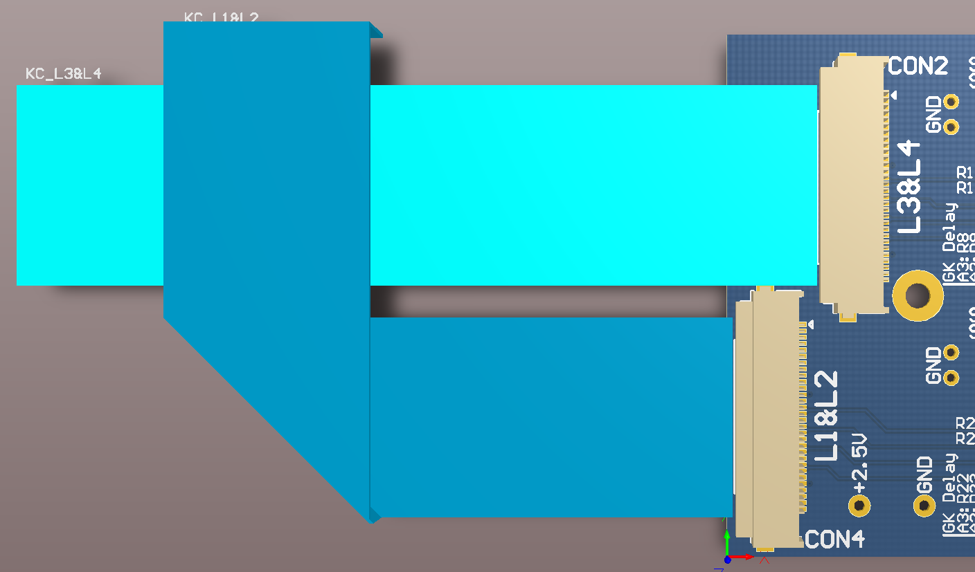
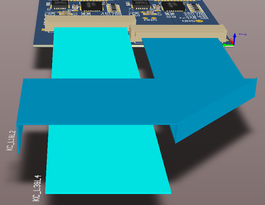
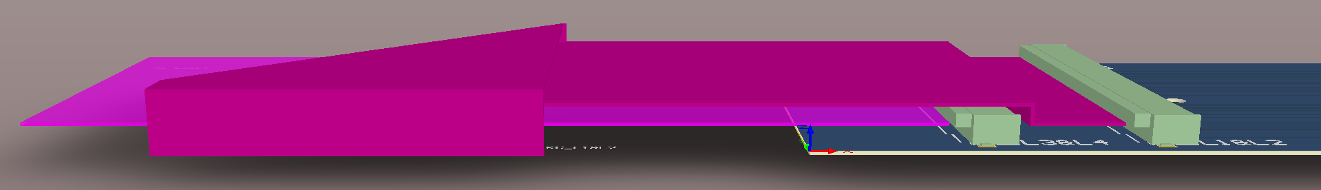
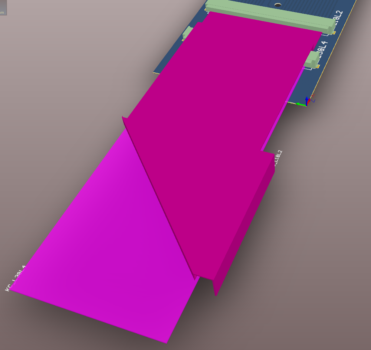
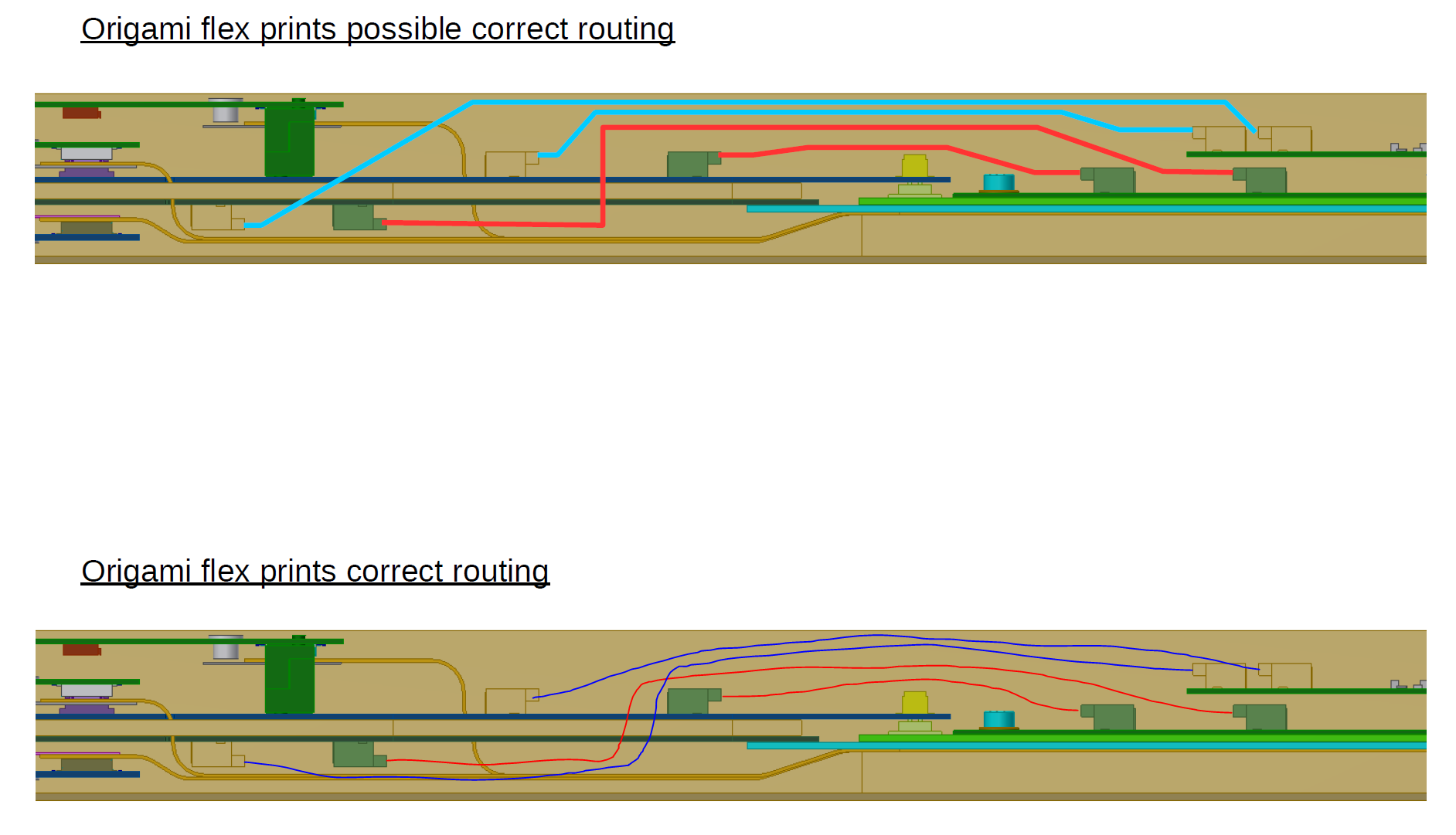
- Connect the origami flex cables:
- Bend the origami flex cables: http://www.physik.uzh.ch/~leac/CMSPixel/Docs/Origami/FlexCablesBending.pdf
Components
Mapping
- Supply Tube Sector Overview: http://www.physik.uzh.ch/~leac/CMSPixel/Docs/Cabling/BPIXOneSector_new.pdf
- POH-module connections: http://www.physik.uzh.ch/~leac/CMSPixel/Docs/POH/poh-connector-mapping.pdf
- POH bundle connections: http://www.physik.uzh.ch/~leac/CMSPixel/Docs/POH/pohconnections.pdf
- FED channel mapping for ZARLINK receiver: http://www.physik.uzh.ch/~leac/CMSPixel/Docs/FED/FED_configuration_map.pdf
- FED channel mapping for FITEL receiver: http://www.physik.uzh.ch/~leac/CMSPixel/Docs/FED/UnterschiedeZARLINKPIGGY.pdf
Manuals
Counting room:
- More information about the optical links: http://arxiv.org/ftp/arxiv/papers/1004/1004.5574.pdf
Supply tube electronics:
- CCU redundnacy scheme: http://www.physik.uzh.ch/~leac/CMSPixel/Docs/CCU/ccu_redundnacy.pdf
- AOH/DOH i2c addressing: http://cms-tk-opto.web.cern.ch/cms-tk-opto/tk/integ/pdf/lld2_i2c_communication.pdf
On detector:
- Module testing reference guide: https://cms-docdb.cern.ch/cgi-bin/DocDB/RetrieveFile?docid=12690&filename=fpix-module-testing-reference-guide.pdf&version=5
DTB:
Power and AUX cabling:
Schematics
- Digital FED ZARLINK Piggy Schematics: http://www.physik.uzh.ch/~leac/CMSPixel/Docs/FED/ZarlinkPIGGY_sch.pdf
- Digital FED FITEL Piggy Schematics: http://www.physik.uzh.ch/~leac/CMSPixel/Docs/FED/PiggyFITELsch.pdf
- Flex Cable DOH L1&2: http://www.physik.uzh.ch/~leac/CMSPixel/Docs/Origami/FCDOHL1&L2v1.1.2.PDF
- Flex Cable DOH L3&4: http://www.physik.uzh.ch/~leac/CMSPixel/Docs/Origami/FCDOHL3&L4v1.1.2.PDF
- Flex Cable POH L1&2: http://www.physik.uzh.ch/~leac/CMSPixel/Docs/Origami/FCPOHL1&L2v1.1.2.PDF
- Flex Cable POH L3&4: http://www.physik.uzh.ch/~leac/CMSPixel/Docs/Origami/FCPOHL3&L4v1.1.2.PDF
- Module connector: http://cms.web.psi.ch/phase1/hdi/Connector_HDI_BPIX.pdf
- UZH Adapterboard L2-L2: http://www.physik.uzh.ch/~leac/CMSPixel/Docs/UZHTestboards/Adapters/Adapter_L2_L2_SCH_Simple.pdf
- UZH Adapterboard L2-L1: http://www.physik.uzh.ch/~leac/CMSPixel/Docs/UZHTestboards/Adapters/Adapter_L2_L1_SCH_Simple.pdf
- UZH Adapterboard 2L2-L1: http://www.physik.uzh.ch/~leac/CMSPixel/Docs/UZHTestboards/Adapters/Adapter_2_L2_L1_SCH_Simple.pdf
- Pinout of DTB connector: http://www.physik.uzh.ch/~leac/CMSPixel/Docs/DTB/DTB_test_adapter.pdf
- Module adapter card ETH: http://www.physik.uzh.ch/~leac/CMSPixel/Docs/DTB/module-adapter-tb.pdf
- Endring print of Phase 0 system: http://www.physik.uzh.ch/~leac/CMSPixel/Docs/endring/x+1N-8N12V10.pdf
PCB Drawing
- Digital FED ZARLINK Piggy Probe pins: http://www.physik.uzh.ch/~leac/CMSPixel/Docs/FED/piggyTestpins_31102014.pdf
- Digital FED ZARLINK Piggy Board Drawing: http://www.physik.uzh.ch/~leac/CMSPixel/Docs/FED/ZarlinkPIGGY_pcb.pdf
- Digital FED FITEL Piggy Board Drawing: http://www.physik.uzh.ch/~leac/CMSPixel/Docs/FED/PiggyFITELpcb.pdf
- DCDC converter (V12): http://www.physik.uzh.ch/~leac/CMSPixel/Docs/DCDC/PIX_V12A_Etchlayer1TopAssembly.pdf
- Extension board B1: http://www.physik.uzh.ch/~leac/CMSPixel/Docs/DCDC/DCDC_Bus_B1_V5_Doku.pdf
- Extension board B2: http://www.physik.uzh.ch/~leac/CMSPixel/Docs/DCDC/DCDC_Bus_B2_V3_Doku.pdf
- UZH Adapterboard L2-L2: http://www.physik.uzh.ch/~leac/CMSPixel/Docs/UZHTestboards/Adapters/Adapter_L2_L2_PCB_Simple.pdf
- UZH Adapterboard L2-L1: http://www.physik.uzh.ch/~leac/CMSPixel/Docs/UZHTestboards/Adapters/Adapter_L2_L1_PCB_Simple.pdf
- UZH Adapterboard 2L2-L1: http://www.physik.uzh.ch/~leac/CMSPixel/Docs/UZHTestboards/Adapters/Adapter_2_L2_L1_PCB_Simple.pdf
Test Results
- ETH Module Testing Database: http://cmspixel.phys.ethz.ch/MoReWeb_Phase_I/Overview/Overview.html
- Phase 1 BPIX module testing database: http://cmspixelprod.pi.infn.it/
- POH test result from ETH: http://www.physik.uzh.ch/~leac/CMSPixel/Docs/POH/POH_ETH.csv
Links
- Danek's CERN page: http://dkotlins.web.cern.ch/dkotlins/CMS/
- Wolfram's PSI page: http://cms.web.psi.ch/phase1/
- CMS tracker upgrade DOC DB: https://cms-docdb.cern.ch/cgi-bin/DocDB/ListBy?topicid=339
- Tivadar's page: http://www.rmki.kfki.hu/~tivadar/CMS_BPIX_ST/
- ETH CMS pixel group: http://cmspixel.phys.ethz.ch
- ETH Graphite Browser: http://cmspixel2.ethz.ch:8018/
Results
Related Talks and Documents
Project Reviews
- June 2016 - Installation EDR: https://indico.cern.ch/event/539704/
- April 2016 - MPR: https://indico.cern.ch/event/520167/
- June 2015 - MPR: https://indico.cern.ch/event/385069/
- December 2013 - EDR: https://indico.cern.ch/event/278220/
Our group's talks
2016
- Lea, Group meeting, http://www.physik.uzh.ch/~leac/CMSPixel/Commissioning_UZH.pdf
- Lea, Phase 1 Days Strasbourg - ST status, https://indico.cern.ch/event/533378/contributions/2285462/attachments/1328630/1995592/Phase1_BPIXST_LeaCaminada.pdf
- Lea, Plenary - Phase 1 Days March, https://indico.cern.ch/event/497123/contributions/1176345/attachments/1244946/1832965/Phase1_BPIXST.pdf
- Jennifer, Test Stand - Phase 1 Days March, https://indico.cern.ch/event/505850/contributions/1183788/attachments/1244398/1831892/Jennifer_Phase1Workshop16March2016.pdf
- Lea, Supply Tube - Phase 1 Days March, https://indico.cern.ch/event/505860/contributions/2025234/attachments/1244237/1831535/Phase1_BPIXST_March.pdf
- Lea, Cooling - Phase 1 Days March, https://indico.cern.ch/event/505859/contributions/1183948/attachments/1244128/1831323/BPIXCooling.pdf
- Riccardo, Supply Tube - Phase 1 Days March, https://indico.cern.ch/event/507661/contributions/2020067/attachments/1242788/1828668/BPIX_ST_phase1_Riccardo_Del_Burgo.pdf
- Daniel Hernandez Garland: http://www.physik.uzh.ch/~leac/CMSPixel/Docs/PresentacionJueves-DanielH.pdf
- Lea, Plenary - Tracker Week January, https://indico.cern.ch/event/472715/contributions/1151469/attachments/1219061/1781181/Phase1_STHC.pdf
- Riccardo, Opto - Tracker Week January, https://indico.cern.ch/event/472503/contributions/1151112/attachments/1217544/1778527/optomeetingRDB_Kopie.pdf
- Lea, Installation - Tracker Week January, https://indico.cern.ch/event/472686/contributions/1149197/attachments/1217923/1779568/BPIXCooling.pdf
- Lea, Supply Tube - Tracker Week January, https://indico.cern.ch/event/472687/contributions/1151427/attachments/1217960/1779573/Phase1_ST_Kopie.pdf
2015
- Lea, Plenary - Tracker Upgradre Week November, https://indico.cern.ch/event/448593/contributions/1943266/attachments/1186062/1719534/Phase1STHC.pdf
- Lea, Supply Tube - Tracker Upgrade Week November, https://indico.cern.ch/event/452848/contributions/1962034/attachments/1185034/1717516/UZHST.pdf
- Lea, Installation & Commissioning - Tracker Upgrade Week November, https://indico.cern.ch/event/452847/contributions/1120567/attachments/1185029/1717505/BPixelTools.pdf
- Lea, Cooling - Tracker Upgrade Week November, https://indico.cern.ch/event/452852/contributions/1962048/attachments/1185027/1717500/BPIXCooling.pdf
- Jennifer, Opto - Tracker Upgrade Week November, https://indico.cern.ch/event/453090/contributions/1117777/attachments/1184870/1717334/Jennifer_TrackerWeek_10Nov2015.pdf
- Yong, DAQ - Tracker Upgrade Week November, https://indico.cern.ch/event/453101/contributions/1950410/attachments/1184765/1716997/ph1daq_uzh_nov102015.pdf
- Lea, Tracker General - CMS Week October, https://indico.cern.ch/event/453198/contributions/1117880/attachments/1173448/1695257/Phase1_LC_talk.pdf
- Deborah, Power - Tracker Week July, https://indico.cern.ch/event/396763/contributions/949040/attachments/1125000/1605769/CMS_tracker_week_-_Pixel_Phase-1_Power_Meeting.pdf
- Jennifer, Supply Tube - Tracker Week July, https://indico.cern.ch/event/396762/contributions/942782/attachments/1124949/1605691/UZHTestSystem_Jennifer.pdf
- Deboarh, Supply Tube - Phase 1 Workshop Visegrad, https://indico.cern.ch/event/368934/session/7/contribution/40/material/slides/0.pdf
- Jennifer, Supply Tube - Phase 1 Workshop Visegrad, https://indico.cern.ch/event/368934/session/8/contribution/49/material/slides/0.pdf
- Lea, Plenary - Phase 1 Workshop Visegrad, https://indico.cern.ch/event/368934/session/12/contribution/3/material/slides/0.pdf
- Lea, Tracker General - CMS Week May: https://indico.cern.ch/event/389533/session/0/contribution/1/material/slides/0.pdf
- Jennifer, Opto - January Tracker Week: https://indico.cern.ch/event/361109/contribution/3/material/slides/0.pdf
- Peter, CO2 - January Tracker Week: https://indico.cern.ch/event/360855/contribution/2/material/slides/0.pdf
- Lea, Supply Tube - January Tracker Week: https://indico.cern.ch/event/360858/contribution/0/material/slides/0.pdf
2014
- Peter, CO2, Novemeber Tracker Week: https://indico.cern.ch/event/348917/contribution/3/material/slides/2.pdf
- Lea, Supply Tube, Phase 1 Days: https://indico.cern.ch/event/341564/contribution/2/material/slides/0.pdf
- Lea, DAQ, Phase 1 Days: https://indico.cern.ch/event/342496/contribution/7/material/slides/0.pdf
- Lea, CO2, Phase 1 Days: https://indico.cern.ch/event/341562/contribution/1/material/slides/0.pdf
- Lea, Overview, July Tracker Week: https://indico.cern.ch/event/325474/contribution/13/material/slides/0.pdf
- Lea, Power, May Tracker Week: https://indico.cern.ch/event/316325/contribution/6/material/slides/0.pdf
Other talks and Documents
FPIX Portcard testing
POH
- Werner Lustermann: Phase I Optolink Meeting Sept '14,Phase I Optolink Meeting Feb '14
- Christoph Naegeli's Thesis: http://e-collection.library.ethz.ch/view/eth:8187
Workshops
TDR
phase1/phase1.1487168867.txt.gz · Last modified: by leac
Except where otherwise noted, content on this wiki is licensed under the following license: CC Attribution-Share Alike 4.0 International
